IRSense Guard | Obstacle Detection | Sense an Object in Front of an IR Sensor

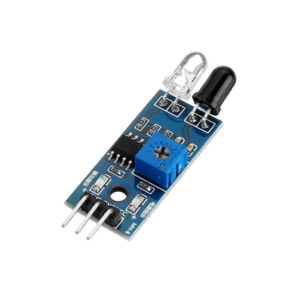
In this project, you’ll create a simple circuit that uses an IR (Infrared) sensor to detect objects. The circuit works by lighting up an LED whenever the sensor detects something in front of it. This is an excellent project for beginners to learn how sensors and LEDs function together in basic electronics.
Materials You Will Need:
- IR sensor module (for object detection)
- LED (any color)
- 330Ω resistor
- Breadboard (for circuit assembly)
- 9V battery and battery clip
- Jumper wires
Step 1: Understanding the IR Sensor
Before you begin building the circuit, it’s important to know how an IR sensor works. The sensor emits infrared light that reflects back when an object is nearby. When the reflected light is detected, the sensor sends a signal through its output pin.
The IR sensor module has three main pins:
- VCC: Connects to the power supply (positive terminal).
- GND: Connects to ground (negative terminal).
- OUT: This pin sends the signal when an object is detected.
Step 2: Setting Up the IR Sensor on the Breadboard
Start by placing the IR sensor on the breadboard. Then, follow these steps:
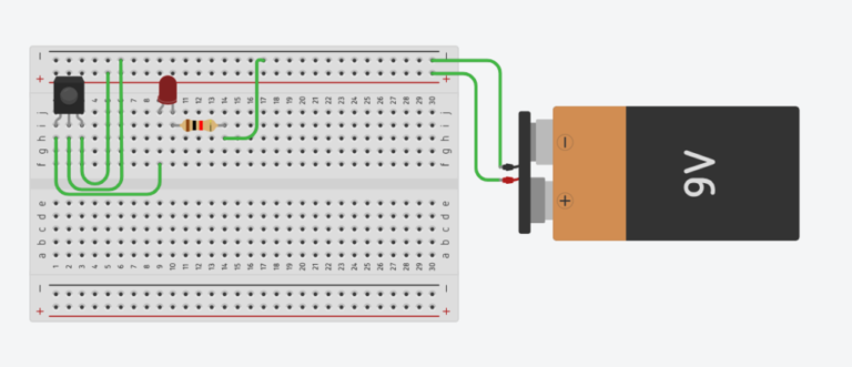
- Connect the VCC pin of the IR sensor to the positive power rail on the breadboard.
- Attach the GND pin to the negative power rail.
- Leave the OUT pin unconnected for now, as you will connect it to the LED later on.
Step 3: Adding the LED and Resistor
Next, set up the LED and resistor:
- Place the long leg (positive) of the LED in Row A of the breadboard.
- Insert the short leg (negative) of the LED into Row B.
- Connect one end of the 330Ω resistor to Row B (where the short leg of the LED is).
- Finally, place the other end of the resistor into the negative power rail on the breadboard.
Step 4: Wiring the IR Sensor to the LED
At this stage, you’ll connect the sensor to the LED so it lights up when an object is detected:
- Use a jumper wire to connect the OUT pin of the IR sensor to Row A (where the long leg of the LED is).
Now, when the sensor detects an object, the signal will pass through to the LED, causing it to light up.
Step 5: Connecting the Battery to Power the Circuit
It’s time to power your circuit:
- Attach the battery clip to the 9V battery.
- Use a jumper wire to connect the positive wire (red) from the battery to the positive rail on the breadboard.
- Connect the negative wire (black) from the battery to the negative rail on the breadboard, completing the circuit.

Circuit Diagram
Step 6: Testing the IR Sensor Circuit
Once everything is connected, it’s time to test the circuit:
- Power the circuit by attaching the battery.
- Move an object or your hand in front of the IR sensor.
- When the sensor detects the object, the LED should light up!
If the LED doesn’t light up, review your connections to make sure everything is wired correctly.
Conclusion: Completing Your Obstacle Detection Circuit
By following these steps, you’ve successfully built a simple object detection circuit using an IR sensor and LED. This project helps you understand how sensors and basic components like LEDs work together in electronics. Feel free to experiment with more sensors or add additional LEDs to enhance the project!
